You don’t need to be a firmware developer to get started. The RoboAlarms Flasher walks you through connecting your board, wiring your accessories and installing the right software—one clear step at a time.
Coming with the project
The Flasher is in private development alongside the firmware. The first release is being prepared with Windows as the initial focus. There is no public download yet; see the release plan for current availability.
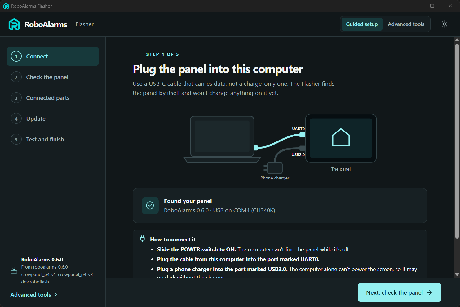
Start with the right connections. Windows app · Development version.View full size ↗
One step at a time
Know where you are. Know what comes next.
Five steps take you from a connected board to a panel you can test. Along the way, the Flasher explains what it found, what your choices mean and what will happen before you continue.
Connect.
Follow the illustrated guide for the power switch, USB data connection and panel power. The app lists connected devices and helps you check cables, drivers and busy ports if yours doesn’t appear.
Check the panel.
The Flasher checks the board and matches it with a firmware build, explaining how it recognized the hardware. If the match is uncertain, you choose. Checking a new board briefly restarts it without changing its software.
Choose connected parts.
Start with a suggested layout or select your receiver and clock module. See where each wire goes, check for conflicting pin choices, and see how many inputs remain for wired zones.
Install or update.
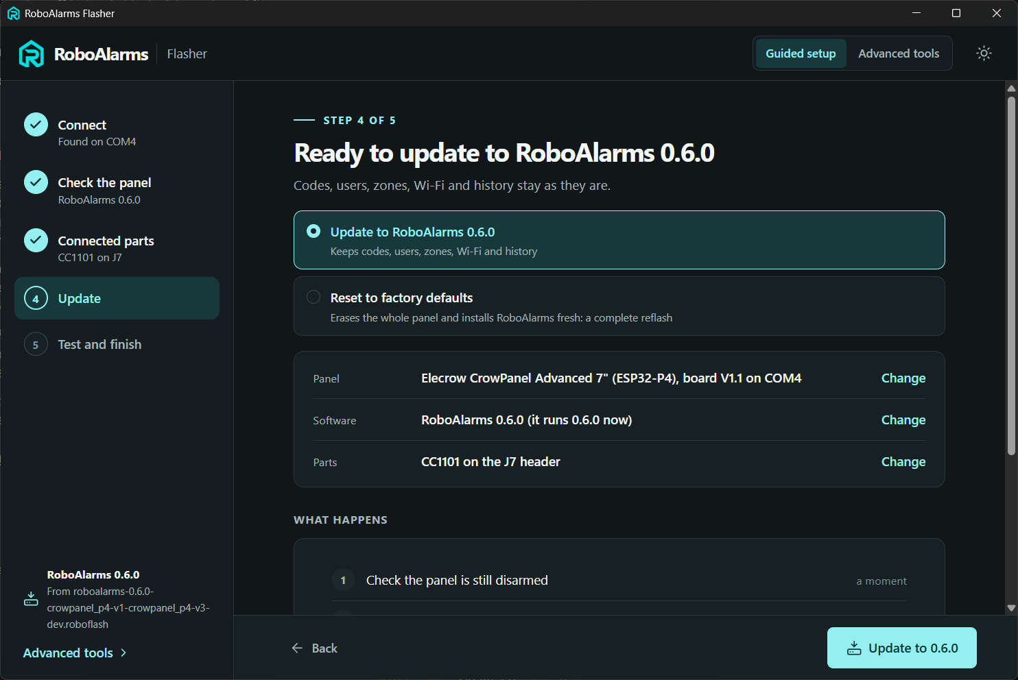
Review your board, software and parts together before starting. A first installation has a full backup selected by default, then walks through writing, verification and startup. Compatible updates preserve your settings.
Test and finish.
Complete first-time setup on the touchscreen, then check the connected hardware. Listen for supported 433 MHz devices, inspect the clock module, and confirm the setup before relying on it.
See where every wire goes
Choose your parts. Follow the connections.
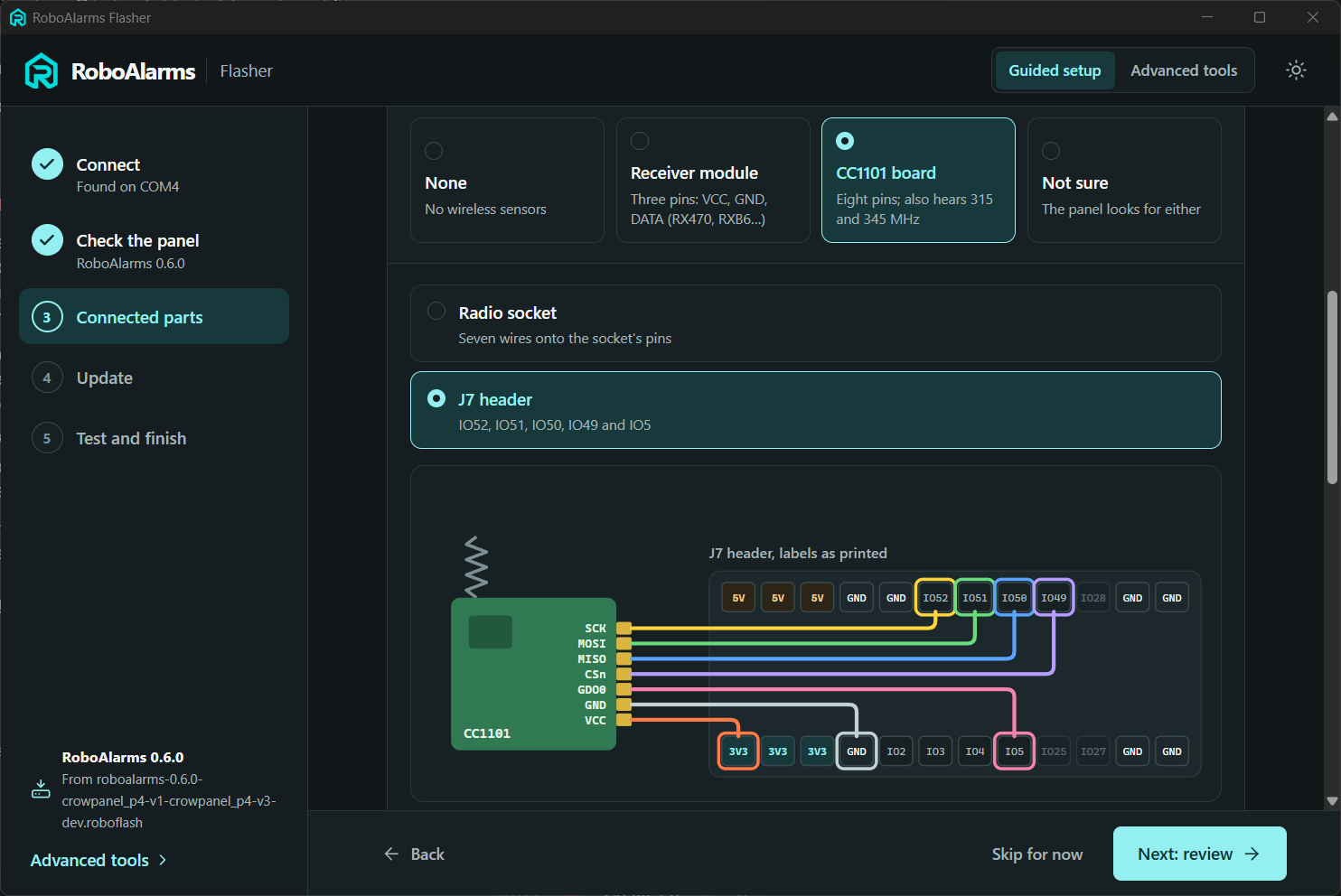
Select a CC1101 and its connection point, and the guide changes with your choice. The J7 view below traces each colored wire from the radio to the labeled panel pin. The app also explains the power and wiring checks for that layout.
CC1101 on J7: your choices become a pin-by-pin guide. Windows app · Development version.View full size ↗
Wiring and settings together
Make the connections. Keep the settings in sync.
Choose a fixed 433 MHz receiver or a CC1101, add an optional DS3231 clock, and start from a suggested layout or choose each connection yourself. The Flasher shows the wiring and applies the matching panel settings after installation.
The guide follows the printed connector labels. Pin order can vary between modules, so match the labels and follow the voltage guidance shown for your parts.
Check the plan
Catch pin conflicts early.
The pin check explains when two choices need the same connection, blocks conflicting layouts, and shows the remaining wired-zone inputs. Suggested layouts provide a starting point; individual choices are available too.
The Zigbee module is included in planning because it occupies the radio socket. Native Zigbee firmware is still in development; selecting the module does not make Zigbee available yet.
These checks validate the selected configuration. They cannot inspect your physical wiring or establish compatibility with every sensor. See supported hardware and testing status ↗
Know what will change
Install. Update. Reset. Clearly different choices.
The Flasher explains what each operation keeps and what it erases before you start. Backups and restore tools are available when you need them.
Review the board, software and connected parts before you start. Windows app · Development version.View full size ↗
First installation
Keep a way back.
A fresh installation replaces the board’s existing software and data. The Flasher offers a full backup first and checks that copy before erasing and writing RoboAlarms.
Keep that backup if you want to restore the manufacturer’s original demo. Installing RoboAlarms does not preserve the demo or its settings on the board.
Compatible update
Keep your setup.
For a compatible update, codes, users, zones, Wi-Fi and event history stay in place. The Flasher checks the existing storage layout before allowing an update that preserves settings.
If the new firmware needs a different storage layout, it requires a fresh installation with a clear data-loss warning. Updating is permitted only when the running panel is disarmed and idle.
Factory reset
A deliberate fresh start.
Reset to factory defaults erases the whole panel and installs RoboAlarms again. Codes, users, zones, Wi-Fi, integrations and event history are removed, and first-time setup starts over.
The erase choice requires an explicit acknowledgment and confirmation. You can choose to keep a full copy of the current panel before resetting it.
Backup and restore
Your copy stays with you.
Full flash backups are saved on your computer with information about the board they came from. Restore checks the target chip and memory size and asks before using a copy from a different panel.
A full backup can include alarm configuration and credentials. Keep it somewhere private and retain the original factory backup separately.
From progress to checks
Follow the progress. Check the result.
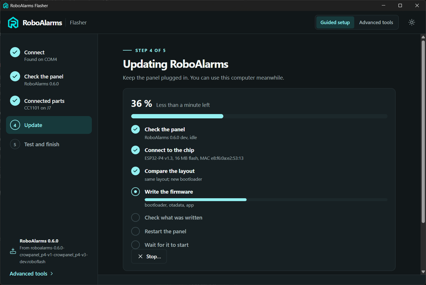
See which checks have passed, what the Flasher is doing now and what comes next. After installation, the same app helps you test connected parts and troubleshoot your setup.
Follow each stage, from checking the panel to writing, verifying and restarting. Windows app · Development version.View full size ↗
Radio and clock checks
See what the panel hears.
Start listening, then open a sensor or press a remote to inspect received 433 MHz messages. The clock check compares the optional DS3231 with your computer’s time and provides a way to set it.
Receiving a message is one step in testing a sensor. Learning its codes and assigning it to a zone happens on the panel, followed by testing that zone’s behavior.
Advanced tools
Details when you need them.
Inspect ports and board information, open a firmware bundle, review logs, manage backups, or adjust connected parts on a running panel. Compatible development firmware also provides a service console for diagnostics.
The Flasher works over USB. For everyday operation and configuration over your local network, use Panel Manager, the browser interface hosted by the alarm panel.
Built, tested, still developing
Preparing for the first release.
An earlier Flasher version has been used to install a real development panel. The newer guided setup, wiring checks and reset flow have been exercised with automated software tests and simulated panels. The redesigned flow and new hardware layouts still need their physical acceptance checks.
Windows is the initial focus. macOS and Linux packaging paths exist, but they are not being presented as validated releases. Development remains private while the first public release is prepared.